Columns Matter, Too: How to Improve Nano and Microflow LC-MS Proteomics by Considering the Separation Itself
Part 1: How a trap-and-elute configuration can solve many problems in proteomic nanoflow and microflow LC-MS
In discussions with scientists who are actively working with nanoscale and microflow LC-MS systems (e.g., in proteomics and peptide mapping), I find it interesting that a great amount of effort is spent on system setup, such as fluid connections or the MS data collection parameters.
While these are obviously important, what’s surprising to me is that comparatively little time is spent considering the choice of stationary phases for trap and analytical columns. It’s a peptide – so you’re going to just use C18 columns, right? Not exactly.
In my three-part series, let’s explore how an optimal pairing of stationary phases can greatly improve your nanoflow and microflow LC-MS results.
- Part 1: How to Improve Nano and Microflow LC-MS Proteomics by Considering the Separation Itself
- Part 2: Choosing the Best Stationary Phase for NanoFlow and Microflow LC-MS
- Part 3: Optimizing trapping conditions
When considering nano and micro column choices, two aspects are often overlooked:
- Trapping and the different sets of trapping configurations, which all have a specific purpose and help the scientist to reach their goal of optimized separations and sample throughput
- Choosing a stationary phase and combinations of stationary phases for trap columns and analytical columns and the impact this can have on the outcome of the analysis, from resolution, peak width, and peak capacity to essentially the number of identified peptides or other species of interest.
Let’s take a closer look at the basics of trapping and the advantages and considerations for implementing a trapping step in a LC separation.
We know that nano- and microflow LC-MS takes advantage of the miniaturization of the chromatography and the LC-MS interface in at least two significant ways. The small sample volumes and the efficient ionization and MS sampling, as well as oftentimes reduced matrix effects, have both a positive impact on the signal-to-noise ratio, or the sensitivity, of the LC-MS assay.
Volumetric problems in nano- and microflow LC-MS
However, the improved sensitivity of nanoLC assays can easily be compromised by poor experimental methods. The reduced column volume makes nano- and microflow LC more vulnerable to incompatibilities in the chromatographic conditions that might have no impact on a larger-scale analytical column.
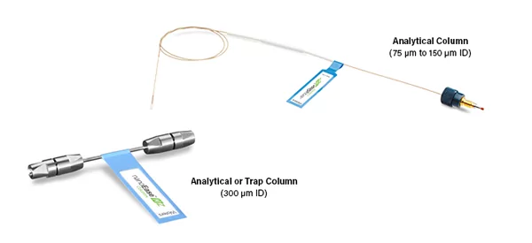
As an example, a 75 µm inner diameter (I.D.) column for nanoLC has a 780-times smaller column volume than a 2.1 mm I.D. analytical column of the same length. Injecting, for example, a 5 µL sample directly on a 75 µm I.D. column would be the same as injecting 3.9 mL sample onto a 2.1 mm I.D. column. And that would most likely turn into a chromatographic mess.
With these injection amounts, particulates or other problematic species such as residual protein or lipids can show their troublesome character within a few injections. The column inlet of the nanoLC column could get blocked or the column packing could foul and lose its retentivity. Also, at these injection volumes, the solvent strength of any upstream (online or offline) sample preparation step could also disrupt the chromatographic separation.
And I’m not even mentioning the incredible long loading times of the sample onto the analytical column: At a typical flow rate of 300 nL/min, it would take about 17 minutes to just flush a 5 µL volume. If the sample loop is larger, the required time will be even longer.
Trap columns
This is where a trap-and-elute configuration solves many problems in proteomic nano- and microflow LC-MS. With this setup, the sample is injected and focused first onto the trap column. A trap column is designed to allow this step to happen at high flow rates in a relatively short period of time by using larger inner diameter hardware and larger particles than the respective analytical column.
The trap filters out impurities or unwanted species in the sample, while retaining the analytes of interest. In the subsequent step, the trapped analytes of interest are reconstituted in the mobile phase and eluted onto the analytical column at the lower flow rate for the analytical separation.
Advantages of trapping:
- Increased loading speed of the sample
- Increased volumetric load and thus higher mass load on the column, resulting in an increased dynamic range of the nanoLC-MS assay
- Additional sample cleanup prior to injection onto the analytical column
Essentially a trap column is a waiting and cleaning area for the injected sample before the components are eluted and further separated with high resolution on the downstream analytical column.
Of course, using trap-and-elute requires a bit of method development. While a well-optimized trapping method can achieve all the benefits described, a poorly designed trapping method can result not only in loss of MS signal strength but also in a loss of the analyte.
Trap-and-elute system configurations
The two main system configurations for trap elute are either forward-trap-elute, which is the most basic setup, or the more sophisticated reverse-trap-elute setup. Each of these setups has their set of advantages and disadvantages.
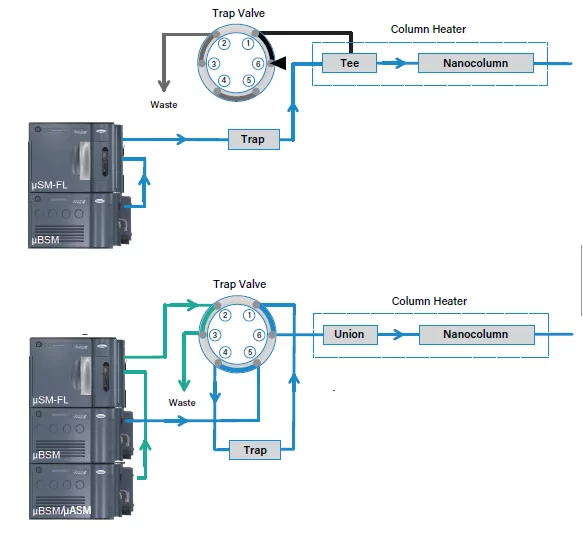
In the forward-trap-elute configuration, the sample is simply loaded from the injection valve onto the trap column, cleaned, and pushed through the outlet of the trap column onto the analytical column. The trap valve enables the flow stream to not reach the analytical column during the loading and cleaning step of the trap. This flow path will be closed and the flow is forced onto the analytical column during the elution step.
In the reverse-trap-elute configuration, the sample will also be loaded onto the trap column in normal flow direction. However, after completion of the loading and cleaning step, the flow direction is reversed by switching the trap valve. The sample is eluted backwards, through the inlet of the trap column onto the analytical column. A secondary pump makes sure that the analytical column is always seeing mobile phase flow, even during the loading step.
Sample loading and eluting
Before diving into trapping and eluting the sample, I just wanted to remind the reader about the van Deemter curve and its meaning for chromatography – it essentially states that if a chromatographic band is migrating along a packed bed at non optimal linear velocity, the chromatographic band experiences severe broadening. This effect is more pronounced for larger particles, e.g., as used in trap columns as it is for smaller particles as used in analytical nano- and microflow columns. The inclined may want to read this superb article about band broadening in chromatography.
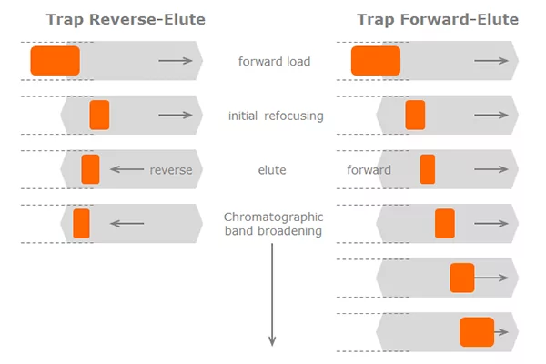
In both cases of trapping, the loading step happens at high flow rates and through the inlet of the trap column. Ideally, the injected analyte band is being retained and therefore somewhat focused near the inlet of the trap column. How well the analytes are being focused and how much column volume they take up depends of course on the hydrophobicity of the analyte.
When eluting, the flow rate is reduced to maximize the efficiency of the analytical separation in the nanocolumn – typically at a very low flow rate suitable for the small bores of the nanocolumn. If the analyte is being eluted in the forward direction (the same direction as the loading flow), the sample has to migrate along the entire length of the trap’s packed bed at a less than optimum velocity (don’t forget that the trap hardware and particles are much larger than those for nanocolumns) – that is a recipe for significant band broadening.
When the trap is eluted in backward flow direction, the analyte band has to only migrate a short distance along the packed bed – the band broadening effect will be significantly less pronounced. This reduced band broadening is a significant benefit of the reverse-trap-elute method. There is a way to somewhat revert the effect of band broadening. The method is not always possible but can be powerful if used properly.
It always depends on your sample and its matrix…
In this post I have addressed the two most common trap-and-elute system configurations and pointed out the potential impact on the quality of the chromatographic separation, depending on whether the simpler forward-trap-elute or the more involved reverse-trap-elute method is being used. The correct answer, of course, is not definite and will differ very much depending on the nature of the sample and the sample matrix. However, I believe the thoughts above should be considered when evaluating your nano- or microflow separation. Because, in the end, we probably all care most about the number of identified proteins and peptides or the accuracy of the quantitation when choosing one method over the other.
In the next post I will discuss the impact of the stationary phases and how to choose the optimum stationary phase for trap-and-elute nano- and microflow LC-MS for peptide analyses.
Additional resources
My colleague Patty Sun wrote two wonderful articles about enhanced sampling efficiency and matrix effects. I recommend reading those for more in depth thoughts about these subjects:
- What is microflow LC
- Microflow LC Offers Better Sensitivity Due to Reduced Matrix Effects
- Nano and Micro LC columns from Waters
- White paper: Considerations for Selecting Optimal Stationary Phases for Proteomic Trap-and-Elute Nanochromatography
- Want a deeper dive? Playback our recent webinar hosted by SelectScience, Considerations for Selecting the Optimal Stationary Phases for Proteomic Trap-and-Elute NanoLC-MS, featuring Moon Chul Jung, Ph.D., from Waters
Related posts
Increasing Lab Efficiency with Amazon Web Services to Enable Real-Time Remote Access to Lab Information
The collaboration between Waters and AWS has enhanced the waters_connect System Monitoring tool, revolutionizing laboratory productivity. This cloud-based platform provides secure, compliant access to chromatography lab information, allowing users to coordinate work, address system errors, and make informed decisions from anywhere, anytime.

The Future of Breast Cancer Screening?
At Waters, we’re constantly innovating our mass spectrometry systems to improve human health, like this groundbreaking advance in breast cancer detection.

Sample Vials Through the Ages
From the 1700’s to the modern age, sample vials have been an integral part of the workflow in analytical laboratories. Today, we still test and certify the whole vial kit.
Popular Topics
ACQUITY QDa (17) bioanalysis (11) biologics (14) biopharma (26) biopharmaceutical (36) biotherapeutics (17) case study (17) chromatography (14) data integrity (22) food analysis (12) HPLC (15) LC-MS (22) liquid chromatography (LC) (20) mass detection (16) mass spectrometry (MS) (54) method development (13) STEM (12) sustainability (12)